ATS Test System Solar Cell Tester


Auction
- Our partner auctioneer is
- Peaker Pattinson
- Part of an Auction
- Clearance Auction
- Lot ID
- MZ689J
- Manufacturer
- ATS
- Model
- Laboratory Solar Tester
- Year of Manufacture
- 2008
- Serial
- 0283
- Condition
- From a working environment, Good Condition
- Capacity
- Cells 150/200mm
- Process Application
- Test Solar Cells
- Other Info
- Clean room quality full document support
- Location
- Rolls Royce stores Unit 6
- External Dimensions (WxDxH mm) [?]
- 1220 x 1220 x 1400
- Delivery Your delivery options
Description
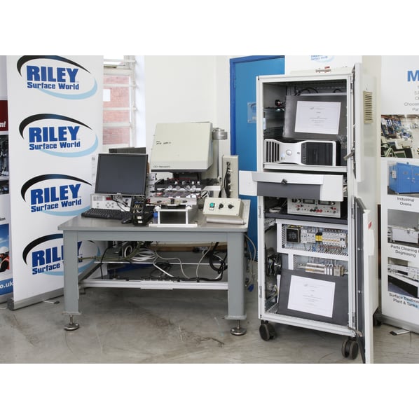
ATS Solar Cell Test System
The following information is taken from the Original Manufacturer specification included in the extensive manuals and documentation accompanying this system. The test system is now available as is and as seen in the photographs.
The Test Stand was built as an ATS standard product photovoltaic cell tester platform that consists of:
- Newport Oriel 93194A 8” x 8" (200mm x 200 mm) Solar Simulator Lamp System (Class A)
- PC Based; National instruments Data Acquisition
- Standard Solar Cell Test Executive Software
A custom vacuum-chuck and Qty (4) adjustable pogo-pin-bus-bars will be included on our standard platform to accommodate testing various sizes of solar cells from 125 x 125 to 200 x 200 mm.
Adjustable bus-bars can move, left or right, to provide preferred contact on the sunny side of the cell to accommodate different bus bar arrangements.
The vacuum-chuck-mask and bus-bar engagement are capable of being adjusted or changed out for future solar cell sizes and shapes that have special connection requirements.
An operator would be required to manually load and unload the cell under test. The cell is placed under the pogo pin tooling. The vacuum-chuck will hold the cell in place while the pogo pins are engaged. The operator will touch the start switch to perform the preconfigured photo cell tests. When the test is complete the pogo-bus-bar-tooling is raised before the operator hinges up the vacuum-chuck-mask to provide easy removal of the photo cell.
Operational Description and List of components
The following is a brief operational description of the Test System . Unless otherwise noted, all components are in quantities of (1).
Test System Fixturing
The Test Stand will include the following fixture details:
1. Purchased table and base capable of supporting the quoted Test System
2. Custom Designed Test Nest will include the following features:
- Manual Loaded and Unload.
- Vacuum gripping of the part.
- Nest will be temperature controlled via water circulation.
- Nickel Plated Copper nest to provide electrical connection to the back of the Cell.
3. Sliding nest will provide access for load/unload of test cell consisting of the following:
- Thomson Linear rails to provided repeatable placement
- Detent (spring or pneumatic activated) for decisive placement of nest slide in the required test position
- Proximity/Pneumatic sensors for detecting slide in correct location before permitting overhead pogo-bus to engage
- Base plate for mounting linear rails and test nest
- Tubing/Cable management throughout stroke of sliding nest
This will allow the next to test nest to manually slide out form under the Oriel to allow the operator unencumbered access to the nest to ease loading of the PV cell. After PV cell has been loaded, the operator manually slides the nest into the test position under the solar simulator.
4. Recirculation water chiller to provide controlled temperature water to the Test Nest.
5. Manual Engaged overhead Pogo Bus Bar:
- Qty(4) overhead Bus-Bars, complete with pogo pins, provided for probing the Solar Cell
- Overhead tooling will be mounted to a linear slide that is lowered and locked in place via pneumatic control.
- For future part type variations Bus-bar locations can be manually adjusted. For different part types the entire overhead Pogo engagement tooling can be changed out.
6. Pneumatic actuated guide Rails for operating vertical motion of Pogo Engagement Tooling engagement
7. Air Preparation Unit including filter & regulator.
Standard Test System Software Features
All software should be accurate, informative, easy to use, fault tolerant, descriptive in its error and warning messages, and above all appropriate for it's intended user.
Includes the following software features to support the Test System:
Perform all tests as defined within the Details of Test. Values measured shall represent the averages of significant data sampling to prevent erroneous readings.
- All measurement results will be archived to hard disk, and data can be shared with a network.
- Test results can be annotated, displayed at test computer, archived, shared with network, and displayed at another remote computer. The file format is non- proprietary and is viewable using any text editor or imported (as Text, CSV or Tab Delimited) into any spreadsheet or database program.
- Pass/Fail determination is user configurable and password protected. An audit file tracks the user and any changes made to system parameters. Configuration files are encoded to provide notification of any unauthorized changes external to the program.
- Display all measured values and Pass/Fail limits on the screen until the next test is performed. Optional graphing capability for display of high-speed data acquisition raw data measurements and ability to save raw data to CSV files for archiving.
- Provide a Pass or Fail indication for operator at end of automatic test.
- Optional retest feature is available for parts that are considered to be marginal.
- Optional ability to review previous test result screens.
- Should a Fail occur, provide a detailed message as to failure condition. Use of large text fonts and colour to provide the operator clear messages and feedback information is provided.
- Provide a running display of number of good parts, failures and related percentages. Can be configured to count summaries by user selectable shift times or Batch number changes.
- Provide archiving of all test results for future SPC analysis and/or warranty analysis in Text format. Test data to be linked to generated serial number for passed units. All archive files are stored in the format YYYYMMDD_*.LOG or CSV. Daily housekeeping of computer hard disk archive files shall be automatic.
- Provide Daily and Weekly Management Reports as to number of parts tested, number passed, number failed, Pareto analysis as to reason for failure. Production shall be reported on a three-shift, hourly basis over all twenty-four hours per day.
- Provide a method to review Days Production Test Data from within the Test System application.
- Configurable limits on alarm measurements. Useful for in-factory modifications due to changes in the environment.
- Configurable hardware scalars and offsets, Useful for hardware calibration adjustments and replacements.--
- Multi-language support. Has a built in-feature to track unknown translations and allow for user modifications and additions.
- Multi-level password security that allows access to different levels of tester control for different user groups.
- Provide detailed Test System diagnostic messages when an abnormal hardware condition is detected.
- Provide System standalone diagnostic software to view and manually activate control all instrumentation electronics to assist in debugging of Test System malfunctions.
- Provide remote operation of Test System and computer control via modem or network to assist the customer when requested. The security of this feature is to be controlled by the customer.
- Provide all customer specific test software main source code listings and licensed copies all linked of source code, MS Visual C++ compiler and Microsoft Windows 2000 Workstation.
- Provide an automatic graphics screen saver for equipment idle time.
- Provide software that is optimized to minimize the Test Cycle Time
![]() Print / Download ATS Test System Solar Cell Tester Datasheet
Print / Download ATS Test System Solar Cell Tester Datasheet
Additional files
Auction Lots Descriptions and photographs are provided in good faith but may not be correct. It is the Customer's responsibility to ensure that the machinery is fit for the purpose for which it is purchased and safe for the purpose of use at work via physical inspection. All sales are deemed to be 'as inspected' and 'as is, in situ' even if the customer has waived the right to inspect.
Machines & equipment for sale
- Surface Treatment
- Cleaning & Degreasing
- Polishing & Belt Linishing
- Mass Finishing
- Ovens & Furnaces
- Process Cooling
- Shot Blasting
- Dust & Fume Extraction
- Air Compressors
- Rectifiers & Transformers
- Miscellaneous
- Latest Stock
- Special Offers
- Direct From Site Clearances
- Auctions
- Brand New Machines
- Available Immediately
- Sell Your Machine
Machine Alert
Get the latest machines emailed directly to you as they become available to buy online. Sign Up Now