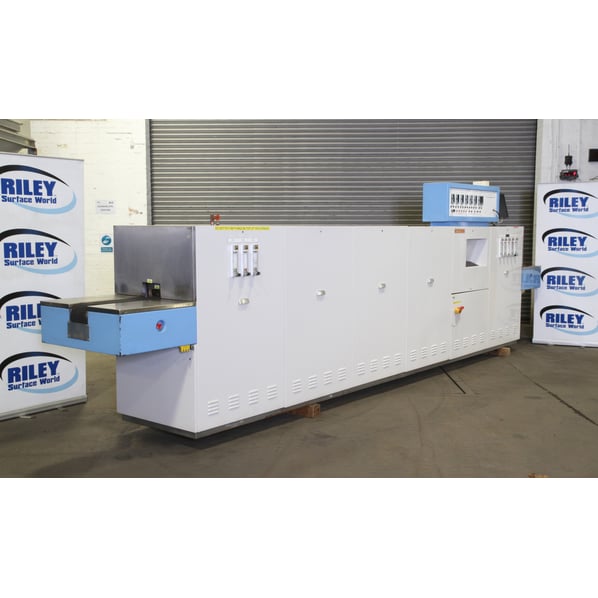
Metritherm 6 Zone Atmosphere Low Temperature Mesh Belt Furnace


- Stock No
- OB2283J
- Manufacturer
- Metritherm
- Model
- 6 Zone
- Year of Manufacture
- Ref 2019
- Serial
- 38881/FS267
- Condition
- From a working environment, Good Condition
- Internal Size (WxDxH mm) [?]
- 150mm Wide belt x 70mm Tall aperture
- Max Temp
- 680°C
- Other Info
- Belt width 150mm
- Location
- Our Central Warehouse, Aldridge, UK
- Weight (kgs)
- 1600
- External Dimensions (WxDxH mm) [?]
- 6560 x 940 x 1440 + control panel at 400
- Delivery Your delivery options
Description
This is a 6 zone atmosphere low temperature conveyor furnace. The furnace was used for glass to metal sealing at 620°C with nitrogen.
Refurbishment
Unit was refurbished by the manufacturer approximately 3 years ago. This was a complete replacement and update on the control system (see below) and a replacement of the cooling section. We understand cost was in the region of £15-20k.
Operation / Specification
- Feed is left to right when facing control system.
- Unit is 6560mm long , 940mm wide, 1440mm high plus 400mm for the control box.
- Belt width is 152mm.
- Belt is 37/18 chrome wire mesh.
- Zones are 286mm in length.
- Working height above belt is 70mm aprox.
- New water jacket fitted on refurb.
- At the same time the control system was upgraded to Eurotherm 3208 controllers, one for each zone displaying actual and set temperature.
- Additional 6 separate over temperature controllers with audible and visual alarm on main control panel.
- Belt speed controller is a Eurotherm 3504 fitted at upgrade.
- All computer linked and accessed via keyboard and screen.
- Motor gearbox 1450rpm 90w 1hp 24 volts.
- CRMI gearbox with torque limiter rate of 1372:1.
Modification Possibilities
- The original build included a Hydrogen supply, which was not required by the previous user and so was disconnected.
- Re-instatement of this hydrogen supply can be made relatively easily as most of the equipment is still fitted.
Furnace Data
Structure & Panelling
- The structure of the furnace is generally of mild steel with 18/8 stainless steel table tops and end fascia panels.
- The structural sections are welded and designed to give rigid floor support with the ability for shim levelling.
- The base frame is designed to give total lift support.
- Separation points where provided give structural integrity with bolted construction.
- General panelling is of folded 1.5mm sheet steel for strength and rigidity.
- Removable panels are size limited for ease of handling.
- All panels are secured with set-screws and bonded for electrical safety.
- Mild steel panels are primed and stove enamelled to clients designated colours.
- Structural integrity is demonstrated by assembly test procedures before shipment.
- The centre of gravity is low for stability.
Insulation & Refractories
Element Tile
Press moulded and fired Sillimanite of proprietary manufacture.
Insulation
Layered and graded ceramic fibre panels of bonded Alumina - Silica composition. Applied to give minimal heat losses heat with low thermal content and efficient heat control response.
Service
The insulation materials are selected for operation well within their temperature limits and should retain their properties for the life of the equipment. Access to the muffle and heating elements is through the top of the heating chamber:
Warning
Allow equipment to cool before entering heat chamber to avoid residual heat. It is advisable to use protective clothing, gloves, mask and goggles for personal safety and comfort.
Heating Elements
Manufactured from Kanthal A1 wire, spiral wound coils housed in pairs of Sillimanite tiles surrounding the muffle. The resistance heaters are designed for longevity with attention to low watts dissipation, good watts to metal ratio and space factor. Working well within its temperature limitation.
Muffle System
- The muffle is the working chamber of the furnace and provides an atmosphere envelope independent of room atmosphere.
- The muffle is fabricated from stainless steel and immaculate V heat resisting alloy.
- Great care in the welded assembly assures the alignment and flatness for conveyor belt tracking.
- No protrusions within the muffle profile to impede the passing of product.
- The disposition of heaters and muffle supports, together with the structured shape minimises the potential for distortion during heating.
- The muffle being in one piece will be subject to expansion, the inlet end is clamped therefore the expansion is directed to the exit end.
Atmosphere distribution
- Obtained by introduction through welded sockets and is disposed to inlet purge chambers to inhibit air ingress, the main atmosphere fed to a distribution tube in the muffle apex to ensure a turbulent dispersal around product.
- Two ‘bum off vents ensures that combustible gases are given off as visual evidence of controlled atmosphere cover and distribution.
- The whole muffle envelope is dye penetrate tested, the material and welded configurations ensure the longest possible stress free life at elevated temperatures.
- Cooling fins are provided at exit slow cool to give efficiency of heat loss.
- Entrance and exit curtain assemblies are fitted to minimise end orifices to promote safety of operation.
- A water jacket is fitted at the entrance end to eliminate potential of pre-oxidation of product and assist in the balancing of the muffle atmosphere.
- Exit water jackets to reduce product temperature to meet dynamic profile requirements and discharge temperature levels.
- Water cooling should preferably be demineralised and recirculated. Excessive flow could cause external surface condensation.
- Waterflow should be controlled to meet full load profile considerations.
- Should the water jackets be subject to mineral deposit blockage - a 24 hour soak with 50% acetic acid and water solution should free it.
- The water jackets are designed to avoid the stress corrosion weld leak problems that can occur but high water pressure may cause the jackets to distort.
Atmosphere Control
- The furnace is designed to provide a controllable gas atmosphere enabling production conformity in safety.
- In general the muffle has 3 atmosphere sections:- Inlet and exit purge chambers and the elevated temperature gas envelope where processing takes place.
- Hydrogen atmospheres cannot bum unless oxygen is present therefore; the normal functions provide for an oxygen free processing environment.
- The hydrogen or combustible gas is distributed in the muffle between two ‘take off points acting like thermal chimneys. Venting hydrogen is raised to a point above datum to give proper stack effect and provide operator safety .
- Hydrogen is burnt at the top of the stacks and is an indication that hydrogen is distributed between these two points. The stacks have valves for adjustment to enable an even flame height of approximately 100mm , unless hydrogen enrichment is a process requirement.
- Avoidance of flame impingement is desirable particularly underneath, sprinklers, gas distribution tubes, fluorescent lights, cable trouncing etc.
- Heat dispersment plates are recommended, 500mm square mild steel plates hung on jack chain over the bum off flame about 450mm above it.
- It should also be noted that burning hydrogen is a heat generator and must be added to the normal furnace losses entering the room.
Supplies
Hydrogen and Nitrogen supplies in a pressure regulated form should be connected to the marked positions on the furnace, the joints being tested for leaks. Applied maximum pressure 2 bar.
Note:- The nitrogen supply is key to safety, it is used to exclude oxygen prior to the introduction of the hydrogen and acts as the cover or purge medium until the furnace drops below oxidation temperature. Therefore the bulk supply of nitrogen should always exceed that of the hydrogen.
Fail Safe System
- The gas system will only function if the gas pressures are sensed by the ‘pressure’ switches, the ignitor coils are functioning and the flowmeter valves are set open.
- During normal operation the Nitrogen can free flow to the entrance and exit purge chambers, also to the main muffle.
- The muffle alloy can begin to oxidise above ambient therefore to preclude such an event purging should commence when furnace heating is initiated. Hydrogen should be introduced when the muffle is fully purged, the bum off stacks are open and furnace is at operating temperature.
- The two ‘bum off flame heights should be adjusted to give approximately 100mm of flame. Product mass flow or process requirements may demand extra Hydrogen, increases of curtain flow should be made accordingly.
- Burning Hydrogen will make water but this will be destroyed at the flame point.
- The bum off stacks should not be touched by hand during furnace operation as they will be heated by the escaping gases.
It is considered to be dangerous to attempt to look up the muffle during operation, similarly the nitrogen curtains should not be interfered with until the system is under purge.
The fail safe system is designed to eliminate the hydrogen should the following events occur:-
a) Fall in pressure of hydrogen or nitrogen supply.
b) Failure of either or both ignitors.
c) Mains power failure.
In any of these circumstances the furnace reverts to free flow of nitrogen. Remember, gas will only flow if the flowmeter valves are open, processing and idle time rates should be recorded.
A proven method of atmosphere testing apart from process acceptability is to take a square/rectangle of say 16 SWG copper and one of mild steel support the test pieces at 30° to belt and pass through furnace:-
- Bright pinkish copper would indicate an acceptable reducing atmosphere.
- Bright steel indicates oil/sulphur free atmosphere.
- The angled pieces would demonstrate any stratification of atmosphere
- Oxidised upper would indicate an internal water leak, the internal burning of Hydrogen or oxidising atmosphere in the exit chamber.
The muffle is constructed in one piece and tested for leaks, the ends are open to ambient pressure, therefore, the possibility of Oxygen ingress to the muffle is remote, the water jackets are designed not to give water to weld problems, gas balance at curtains will preclude contamination.
Due to the ambient pressure in which the furnace functions the main axis of the furnace
should not be subjected to impinged draughts from doors, windows or fans.
Solenoid Valves -
- Model 8714 NBR 0.5”BSP Ports - Normally Open
- Model 8614 NBR 0.5”BSP Ports - Normally closed
- Pressure Switches - RS 317-134
- Flowmeters - Platon GTV/B/311
- Timer - RS 347-927 delay relay
- Bum-off Elements - Platinum/Platinum 13% rhodium wire
Conveyor System
The furnace conveyor belt is manufactured from 37/18 Nickel Chrome wire selected for strength at elevated temperatures and its resistance to oxidation. Connection is made at one point only with a cross pin.
The belt runs along the base of muffle through the furnace then around the unload end terminal roller and returns via the drive rollers and stainless steel roller tracks mounted within the furnace structure to the loading end terminal roller. The free catenary loop from the pinch roller to the return track is indicative of low belt tension , this loop should not touch the ground , it being a source of potential contamination and wear.
Should in the long term the belt shows signs of wear, reversing to another contact face is suggested.
Should any belt slevedge wire protrude it should be turned into the belt with pliers.
Should the belt become dirty a light vacuum brushing should suffice. Excessive abrasion should be avoided.
The prime mover is a foot mounted single phase geared motor unit fitted with a torque limiter. Transmission is by roller chain and sprockets to a large diameter neoprene covered drive roller and cantilevered pinch roller. The sprockets are fitted with taperlock bushes enabling easy modification of the drive ratio , should the normal belt speed range not suit a particular application. The geared motor unit is secured by parallel channels that enable adjustment of the roller chain tension.
The main roller shafts are mounted in self lubricated bearings and adjustable mounting brackets assist alignment for belt tracking.
Emergency belt stop buttons are positioned at each end of the furnace.
Always that care when inspecting or carrying out maintenance work on the conveyor system for although the gearbox output speed is low (0.5 rpm) even at maximum motor speed , the torque developed by the motor through the gear train is considerable.
Temperature Control
An enclosed fabricated temperature control cabinet is mounted on top of the furnace and positioning over the cooling area to minimise ageing. The instruments are at eye level permitting easy manipulation and viewing.
Each furnace zone is controlled by a Eurotherm type£0ffdigital indicating instrument displaying both set-point and measured temperature, the instruments have 3 term PID action with SELF TUNE and RAMP facilities. Zone power is displayed when the instrument A/M button is pressed.
An RS 422 communications system provides a two-way link between the zone controllers, belt speed controller and installed computer system. Zone set-points, measured values, power levels and belt speed are displayed on the monitor positioned in line with the other instruments in eye-level control cubicle above the cooling section of the furnace.
Established process values can be stored by the computer as RECIPES, simply by SNAP SHOOTING the current screen values shown on the monitor. Recipes may also be written directly on the computer and down-loaded to the instruments when required. The keyboard is mounted on the furnace side panel below the instrument cubicle with the computer housed inside the furnace structure.
All control switches and indicating lights are logically positioned and labelled for easy identification. Access to the instrumentation terminals and wiring is from the rear of the control cubicle by removal of a screwed panel. Eurotherm instruments can be withdrawn at the front from their mounting sleeves enabling easy fault finding and replacement. The instrument control circuit is protected by primary fusing in the switchgear cubical.
Thermocouples - Each zone is fitted with two thermocouples (1 control and 1 excess), these are located in the roof of the chamber and pass through the layers of thermal insulation material and element tiles, so that the tip or hot junction is just above the furnace muffle. All thermocouples are type N mineral insulated with PVC covered tails taken to ceramic terminal blocks for routing back to the instruments with compensating cable. An open circuit thermocouple will automatically shut-down the furnace.
Power Control
The electric furnace incorporates heating elements of Kanthal A1 resistance wire disposal in six separately controlled zones, rated to suit required temperature, dynamic load and heat losses. Zones are phase selected to give best case balanced load in production steady state conditions.
Each zone is controlled via a contactor feeding a Eurotherm thyristor power controller. High speed thyristor fuses protect each power controller . All connections by Tri-rated cable and rated at 25% above designed maximum requirement.
Switching of the thyristor units is controlled by the Eurotherm 808 instruments, these provide a logic signal proportional to the power required to compensate for any temperature difference between the set-point of the zone controller and its measured value obtained from the thermocouple within the heating chamber.
In the event of an excess temperature condition , the second thermocouple and backup Eurotherm 92 control instrument will de-energise the zone contactor , thereby cutting power to that zone .
The power controllers and protection fuses are mounted on Din-rail from a panel located below the furnace heating chamber , units being positioned in-line with their respective zones to enable rapid identification and short secondary cable runs.
Access to the power control units may be gained by removal of the rear furnace panels but extreme care must be taken if power has not been isolated for testing purposes. The firing signal from the zone control instruments can be observed by the red signal lamp on each power controller. In the event of a suspected zone failure, the power input to and from the fuse and thyristor units will be good indicators in the fault finding procedure.
Switchgear and Wiring
The switchgear cabinet is constructed within the furnace framework , integral with cable ducting and ensures complete separation from other areas of the equipment.
Access to the cabinet is via a sheet steel door fitted with a door interlocked electrical isolator which ensures total power cut off before the possibility of door opening. The isolator is rated in excess of total power and the 3 phase 4 wire mains supply must be connected to its lower terminals.
Excess Temperature Protection
In the event of accidental overheating of any zone, protection of the heating elements chamber and muffle is given by independent zone control instruments and thermocouples, arranged to interrupt the power supply to the effected zone at a pre-set level.
The Eurotherm type 92 digital instruments are mounted on a panel housed within the lower part of the furnace adjacent to the switchgear cubicle, thus preventing easy or unauthorised access.
An over-temperature condition is shown on the main control panel by the zone amber excess temperature alarm lamp.
Instrument Programming System
The Eurotherm IPS software provides an effective low cost method for storage of process recipes; the zone set-points and belt speed values that create the temperature profile required to process a device or material.
Information from each zone controller and the conveyor drive unit is transmitted by the RS 422 communications link and serial interface unit type 261 to a computer with standard keyboard and monochrome monitor. This two-way link gives a mirrored response, enabling to operator to change set values at instrument or computer level.
After final adjustments have been made to each instrument and the profile results are checked, the set-points can be stored in the computer memory by Snap-shot. The information is then given a recipe name or number and can be retrieved on demand and down-loaded back to the instruments when required.
![]() Print / Download Metritherm 6 Zone Atmosphere Low Temperature Mesh Belt Furnace Datasheet
Print / Download Metritherm 6 Zone Atmosphere Low Temperature Mesh Belt Furnace Datasheet
Additional files
Photographs taken prior refurbishment. Our refurbishment service is not available on all machines.
Machines & equipment for sale
- Surface Treatment
- Cleaning & Degreasing
- Polishing & Belt Linishing
- Mass Finishing
- Ovens & Furnaces
- Process Cooling
- Shot Blasting
- Dust & Fume Extraction
- Air Compressors
- Rectifiers & Transformers
- Miscellaneous
- Latest Stock
- Special Offers
- Direct From Site Clearances
- Auctions
- Brand New Machines
- Available Immediately
- Sell Your Machine
Machine Alert
Get the latest machines emailed directly to you as they become available to buy online. Sign Up Now