Balco Engineering Ltd Acid Anodising Plating Line


Direct From Site Clearance
- Price [?]
- Please call on +44 (0) 1922 45 8000
- Buyer's Premium [?]
- 15% BP will be added to your invoice
- Part of a Direct Site Clearance
- Sulphuric Acid Anodising Line
- Condition
- From a working environment, Seen working by RSW, Excellent Condition, Current Model
- Location
- Belfast, Northern Ireland
- Stock No
- ANO500
- Manufacturer
- Balco Engineering Ltd
- Model
- Balco Plating Line
- Year of Manufacture
- 2019
- Serial
- JN10029
- Condition
- From a working environment, Seen working by RSW, Excellent Condition, Current Model
- Work Envelope (WxDxH mm) [?]
- 2400 x 600 x1100
- Process Stages
- 19
- Other Info
- Easy to adapt for alternative processes
- Location
- Belfast, Northern Ireland
- Delivery Your delivery options
Description
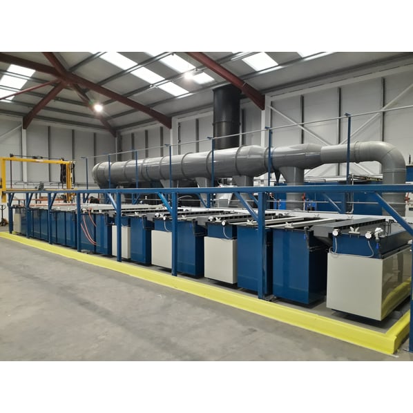
Balco Sulphuric Acid Anodising Plating Line includes 18 large Plating & Rinsing Tanks plus loading & unloading equipment. Complete installation includes Horizontal Fume Scrubber, Effluent Treatment Plant & ICS Chiller.
The sulphuric acid anodising process is still widely used despite the reduction in demand for the process in the aerospace industry by the change from aluminium to composite structures in modern aircraft.
Overview of Anodising Line
Stage 1 - Load/Unload Station
Stage 2 - Soak Clean, 60°C:
- 2400mm x 600mm x 1100mm (800mm solution height)
- Mild steel tank with top flange, externally insulated and over clad.
- 12kw Heater/s, thermostat, level control.
Stage 3 - Rinse:
- 2400mm x 600mm x 1100mm
- Mild steel, PVC lined, with top flange.
- Inlet corner weir, overflow, drain.
Stage 4 - Etch, 30°C:
- 2400mm x 600mm x 1100mm (800mm solution height)
- Mild steel, PVC lined, with top flange.
- 6kw Heater/s, thermostat, level control.
Stage 5 - Rinse:
- 2400mm x 600mm x 1100mm
- Mild steel, PVC lined, with top flange.
- Inlet corner weir, overflow, drain.
Stage 6 - De Smut, Ambient:
- 2400mm x 600mm x 1100mm (800mm solution height)
- Mild steel, PVC lined, with top flange.
Stage 7 - Rinse:
- 2400mm x 600mm x 1100mm
- Mild steel, PVC lined, with top flange.
- Inlet corner weir, overflow, drain.
Stage 8 - Iridite, 20°C:
- 2400mm x 600mm x 1100mm (800mm solution height)
- Stainless steel tank with top flange.
- 3kw Heater/s, thermostat, level control.
- Eductor pump and associated pipework for agitation.
Stage 9 - Rinse:
- 2400mm x 600mm x 1100mm
- Mild steel, PVC lined, with top flange.
- Inlet corner weir, overflow, drain.
Stage 10 - Sulphuric Anodise, 20°C:
- 2400mm x 800mm x 1100mm (800mm solution height)
- Mild steel, rubber lined, with top flange.
- 3kw Heater/s, thermostat, level control.
- Eductor pump and associated pipework for agitation.
- 3 x anode/cathode bars/rails, includes locators.
- Lead anodes.
- 1500 amp, 25 volt digital rectifier, complete with stand and cable to the tank situated locally.
- 45kw chiller unit with heat exchanger unit, 3 way valve and associated pipework.
Stage 11 - Rinse:
- 2400mm x 600mm x 1100mm
- Mild steel, PVC lined, with top flange.
- Inlet corner weir, overflow, drain.
Stage 12 - Dye 1, 60°C:
- 2400mm x 60mm0 x 1100mm (800mm solution height)
- Mild steel tank, rubber lined with top flange, externally insulated and over clad.
- 12kw Heater/s, thermostat, level control.
Stage 13 - Rinse:
- 2400mm x 600mm x 1100mm
- Mild steel, PVC lined, with top flange.
- Inlet corner weir, overflow, drain.
Stage 14 - Dye 2, 60°C:
- 2400mm x 600mm x 1100mm (800mm solution height)
- Mild steel tank, rubber lined with top flange, externally insulated and over clad.
- 12kw Heater/s, thermostat, level control.
Stage 15 - Rinse:
- 2400mm x 600mm x 1100mm
- Mild steel, PVC lined, with top flange.
- Inlet corner weir, overflow, drain.
Stage 16 - Dye 3, 60°C:
- 2400mm x 600mm x 1100mm (800mm solution height)
- Mild steel tank, Rubber lined with top flange, externally insulated and over clad.
- 12kw Heater/s, thermostat, level control.
Stage 17 - Rinse:
- 2400mm x 600mm x 1100mm
- Mild steel, PVC lined, with top flange.
- Inlet corner weir, overflow, drain.
Stage 18 - Rinse:
- 2400mm x 600mm x 1100mm
- Mild steel, PVC lined, with top flange.
- Inlet corner weir, overflow, drain.
Stage 19 - Hot Seal, 100°C:
- 2400mm x 600mm x 1100mm
- Stainless steel tank with 50mm top flange, externally insulated and over clad in polypropylene.
- 24kw Heater/s, thermostat, level control.
Tank Ancillaries:
- Drip shields between each tank.
- 2 polypropylene bars positioned centrally on all tanks.
- 3 flight bars.
- Tank support floor raft/bearers manufactured in 304 stainless steel.
Track and transporter:
- Transporter unit made of mild steel, complete with raise & lower proximity switches.
- 3 point pick up.
- Maximum SWL 200kg.
- 1 x track, manufactured in 80mm x 80mm box section with base plates.
- End stops.
- Cantilever supports.
- Ties to tanks.
- Catenary brackets.
- Catenary track.
- 3 x 12 core cable.
- Light beams to be fitted along full length of process line and load/unload.
Fume Extraction:
The system is designed to extract 6 off tanks, tank sizes are stated in the specification. Each tank has a single extraction hood.
Each of the 6 risers is flanged to the extraction hood with manual damper control unit before connecting into a common high level manifold and various increased diameters to allow for each additional riser entering the duct. The manifold is fabricated in flanged sections with support body bands.
Each tank with extraction hoods features:
- Direct drive polypropylene fan unit with flanged outlet.
- Flexible inlet connection.
- 4 anti-vibration mounts.
- Fan stand mild steel painted.
The individual extraction hoods connecting to a system made up of:
- Polypropylene stack manufactured in flanged sections (9 metres from floor level with support body bands).
- Velocity cone.
- Bird grid connection.
- 4 LEV test points.
- Roof plate and cravat.
Fume Scrubber (Horizontal)
Manufactured in UV stable black polypropylene, includes square to round inlet.
- 23,400 cfm // 39,500m³/h
- Main body section with 2 x spray manifolds.
- 1 set of filter media cartridges.
- Double bank mist eliminator with drain return and square to round to fan inlet with flexible and clips.
- Sump tank with recirculation pump, associated pipework with no flow switch and inline filter.
- 1 pH probe pocket and dosing inlet connection with pH probe and auto dosing pump.
Plant Control Panel with Automation:
The one control panel powers the following:
- Heaters
- Thermostats
- Heater low level protection
- Eductor pumps
- Extraction fan
- Wash box pH
- Wash box auto dosing pump and no flow
- Transporter
- Rectifier
- Chiller
The control system is set up such that all the control features would be accessed through the Touch Screen HMI and controlled through the PLC.
The temperature set points and general control items are presented on the HMI on a screen per tank basis and an overview page to indicate the plant layout. The layout screens would be static and no moving graphics but some colour changes for items running etc. have been allowed for.
The HMI will handle all the plant alarms these are indicated on an alarm page with the panel showing a common fault lamp only to show that an alarm is present. The alarm sounder and beacon are positioned on the main panel along with the mute button.
The transporter is fully automatic and follow the programs held in the PLC memory. Position tracking would be via a proximity switch detecting strikers at the tank position.
There are currently 10 programs held within the PLC and called up via the HMI as a number to select the plating sequence.
The system is capable of self-checking the work already in the anodising line to ensure the next flight bar has a clear path and does not catch the previous flight bar up and hold the plating process up and cause the items to be in a tank longer than desired. A maximum of three flight bars can be in the system at one time.
Heaters are protected from a float switch located in the heater tank, such when low level is activated the heater will switch off automatically.
Also included is the remote access unit for remote software configuration and diagnostics. This can be either a WIFI signal or wired Ethernet internet connection.
Included is the automatic control of the rectifier.
Effluent Treatment Unit:
- 1 x 2m³ palletised effluent waste water treatment unit complete with control panel
- Reagent tanks
- Pumps
- pH correction tank with stirrer
- pH probe, over flow into settlement tank
Pipework to localised foul drain - Allowing for a waste water collection tank to the rear of the line, approx. 1m³ capacity, includes inlet pipework and transfer pump to waste water treatment unit.
![]() Print / Download Balco Engineering Ltd Acid Anodising Plating Line Datasheet
Print / Download Balco Engineering Ltd Acid Anodising Plating Line Datasheet
Additional files
Photographs taken prior refurbishment. Our refurbishment service is not available on all machines.
Machines & equipment for sale
- Surface Treatment
- Cleaning & Degreasing
- Polishing & Belt Linishing
- Mass Finishing
- Ovens & Furnaces
- Process Cooling
- Shot Blasting
- Dust & Fume Extraction
- Air Compressors
- Rectifiers & Transformers
- Miscellaneous
- Latest Stock
- Special Offers
- Direct From Site Clearances
- Auctions
- Brand New Machines
- Available Immediately
- Sell Your Machine
Machine Alert
Get the latest machines emailed directly to you as they become available to buy online. Sign Up Now